
1/2

Addis Ababa, Yeka, 18/06
6 views
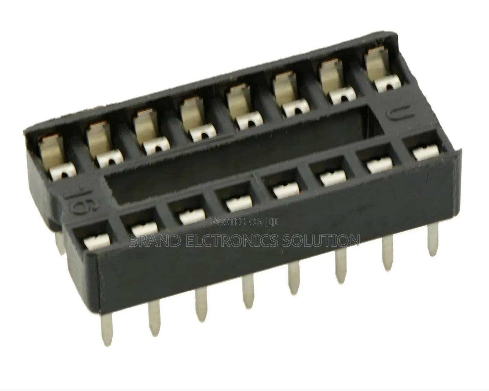
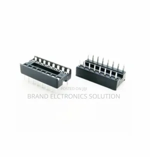
16-Pin Dual Inline Ic Socket
Audio & Music Accessories
Type
Brand New
Condition
16-pin DualIC socket
Brand
Store address
Addis Ababa • Yeka
Megenagnea
Open
• Mon - Sat, 09:00-12:00
Specification overview for a 16-pin Dual Inline Package (DIP) IC socket or base — the standard component used to mount 16-pin DIP integrated circuits on a PCB, protect them from soldering heat, and allow easy insertion/removal:
Standard 16-Pin DIP Socket / Base Specifications
Pin Count: 16 total (8 pins per side)
Pin-to-Pin Pitch (lead spacing): 2.54 mm (0.1′′) — standard for DIP packages
Row-to-Row Spacing: 7.62 mm (0.3′′) (distance between the two parallel rows)
Typical Socket Body Size:
– Length ~20.3 mm
– Width ~10.1 mm
– Height ~4.5–8 mm above PCB
PCB Hole Size: ~0.6 mm diameter (for through-hole pins)
Notch or index marker: most have a notch or dot to mark Pin 1 orientation.
Electrical & Contact Characteristics
Contact Material: phosphor bronze or beryllium copper (springy contacts)

ETB 450
NegotiableETB 380
≥ 15 piecesSafety tips
- Avoid paying in advance, even for delivery
- Meet with the seller at a safe public place
- Inspect the item and ensure it's exactly what you want
- Make sure that the packed item is the one you've inspected
- Only pay if you're satisfied


